


Lighting maintenance and wiring diagrams
Lighting system on the trailer and caravan
Good maintenance of your trailer’s lighting reduces the risk of contact problems and keeps your trailer lighting working reliably on the road. Follow these basic guidelines:
- Apply electrical contact grease on all contact surfaces – bulb contact surfaces, plug contacts, female contacts and cable lugs. Clean contaminated surfaces before applying fresh grease.
- Do not subject your lighting to unnecessary stress from high-pressure washers. If this occurs, remove the lens and wipe off all moisture. Well-greased surfaces reduce the risk of contact problems.
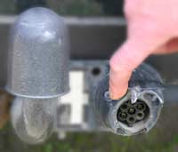
- Take care of plugs and make sure they do not sit in gravel and that water cannot penetrate the connector. Use a plug holder.
- Always keep an extra set of bulbs, plugs, fuses, electrical contact grease, electrician’s screwdriver and a wiring diagram to hand when travelling.
- Always invest in high quality bulbs for your trailer.
Common errors
- Check fuses. If fuses blow repeatedly, check for a short-circuit.
- Undo plugs and make sure the conductors sit firmly in the plug contacts. These frequently loosen when the cord is pulled instead of the plug.
- Use a small screwdriver or knife to separate the pins in the plug. Lubricate with electrical contact grease. Replace the plug if necessary.
- Check female connectors – clean, lubricate and replace when necessary.
- In the event of an earth fault, the electrical system often behaves uncontrollably and flashes irregularly. Make sure all earth connections have good contact, replace cable lugs if necessary and lubricate with electrical contact grease.
Recommended wiring diagram
For 7-way/13-way connection boxes according to standard. On some 7-way boxes there is an extra terminal. Number 8 which is designed to automatically disconnect the fog light on the car and transfer this to the caravan/trailer.
On the 13-way box this is number 2a.
Valeryd does not accept liability for damage caused by improper electrical installation! We recommend that you contact a workshop that has knowledge of electrical installations.
These wiring diagrams show the connection on the car:
7-way ISO 1724
| 1/L | Indicator left (yellow) | ||
| 2 | Fog light (blue) | ||
| 3/31 | Earth (white) 1-7 | ||
| 4/R | Indicator right (green) | ||
| 5/58-R | |
Tail lights right (brown) | |
| 6/54 | |
Brake light (red) | |
| 7/58-L | |
Tail lights left (black) | |
| 8 | |
Switch for dim contact (grey) |
13-way DIN/ISO 11446
| 1/L | Indicator left (yellow) | ||
| 2 | Fog light (blue) | ||
| 2a | Switch for dim contact (grey) | ||
| 3/31 | Earth (white) 1-7 | ||
| 4/R | Indicator right (green) | ||
| 5/58-R | |
Tail lights right (brown) | |
| 6/54 | |
Brake light (red) | |
| 7/58-L | |
Tail lights left (black) | |
| 8 | |
Reversing light (black/red) | |
| 9 | |
Positive terminal cable (brown/white) | |
| 10 | |
Charging cable (red) | |
| 11 | |
Earth to 10 (white) | |
| 12 | |
Trailer present (red/blue) | |
| 13 | |
Earth to 9 (white) |